Equipment Repair Service

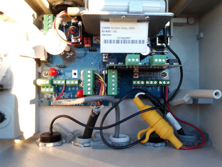
Whether it is a flow meter or a sampler issue we provide onsite troubleshooting and repair service. We stock common repair parts and can help you get back online ASAP.

ISCO Signature Open

Having some preliminary information is the first step in getting ready to eliminate the issue. Planning for troubleshooting visit helps us tentatively identify faulty parts and bring them with us onsite to consequently restore your equipment back to operating condition.


Teledyne ISCO 4700/5800 Samplers

Sampler screen indicating temperature sensor problem

This sampler display indicates that the evaporator temperature sensor has gone bad and both sensors need to be replaced. To find this screen you need to go into the Run Diagnostics.
To start the diagnostics from the Main Menu screen:
1. Select the CONFIGURE option and press Enter.
2. Press the Previous arrow until the RUN DIAGNOSTICS
option is displayed. Press Enter.
3. Select the REFRIG TEMPERATURE option and press Enter.

Sampler screen indicating proper work of the temperature sensors

When this test is started, the sampler will display the temperature until you press the Stop or Enter button. There is no pass or fail. This test simply provides continuous temperature monitoring and cooling/heating. 
The screen here shows temperatures after the temperature sensors have been replaced and the Air temperature is on the way to reaching the target temperature.

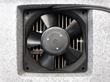
Sampler forced air fan

Forced air fan when it stops working can also cause the sampler to not cool properly due to very poor air exchange between the refrigeration sled evaporator and the sampler bottle. You can determine if the fan is running by reaching inside and putting your hand in front of the fan to feel air flow.  

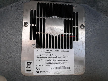
Teledyne ISCO 12VDC Fan For 4700/5800 Samplers

Rear view of the fan.

Sampler refrigeration sled

Sampler refrigeration sled may need to be replaced if the compressor has gone bad. When we replace temperature sensors we check how quickly the Evap temperature drops. If in over 5-7 minutes the Evap temperature has not dropped chances are the refrigeration sled is not working. The picture here shows a properly working refrigeration sled with frost rising from the bottom coils to the top.

Pump Tube

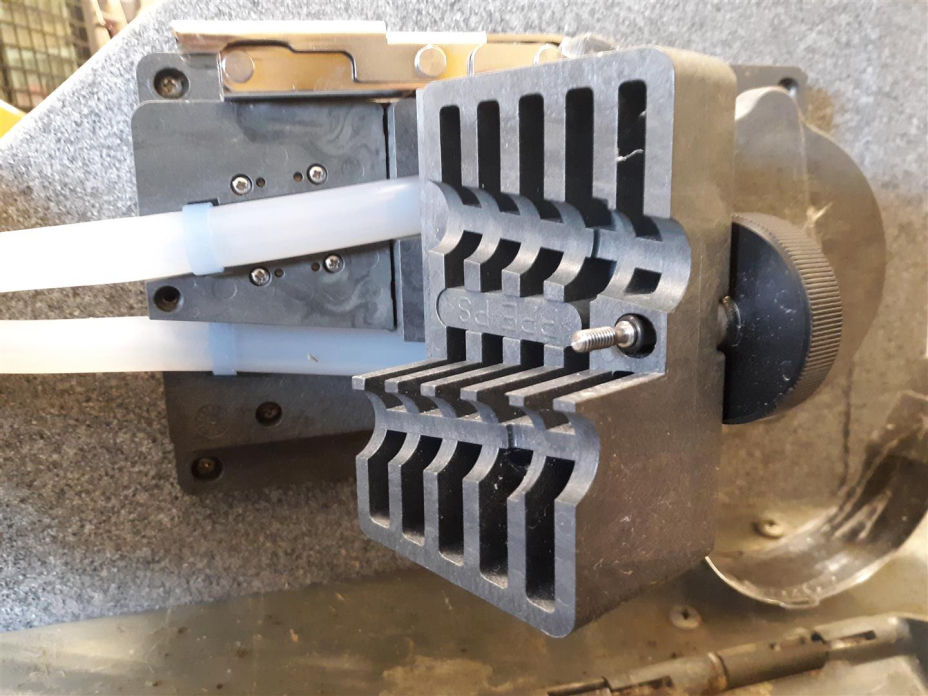
The correct sampler pump tubing is easily recognized by the blue alignment collars. Pump tubing from non-Isco vendors and tubes designed for other types of samplers should not be used. Incorrect pump tubing may result in poor pump performance or even cause parts to fail prematurely. Also note that the discharge tube is not the same as the pump tube.

Among them are:
• Incorrect installation.
• Abrasive materials suspended in sample liquid.
• Frequent line rinses.
• Long purge cycles, such as those used with long suction lines.

Always use Isco pump tubes.
• Install the tube properly, aligning the blue collars correctly in the notches.
• Follow the natural curve of the tube when wrapping the tube around the pump rollers.
• Minimize the line rinses and sampling retries in the sampling programs.
• Use the shortest possible suction line.

Teledyne ISCO Pump Tube Correctly Installed

When replacing the pump tube make sure to align the blue collars with the alignment notches.

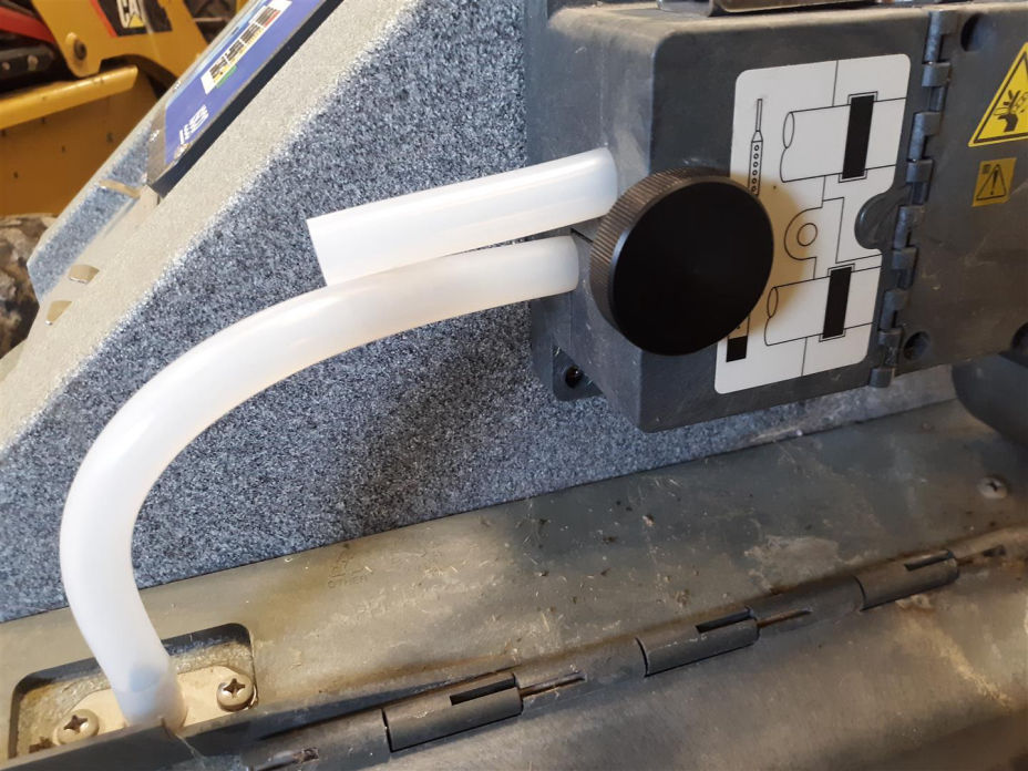
Teledyne ISCO Pump Tube Correctly Installed

Be carefull to follow the picture on the pump assembly door for proper tump tube installation. The top short end connects to the suction line and the long end to the stainless tube on the sampler body.

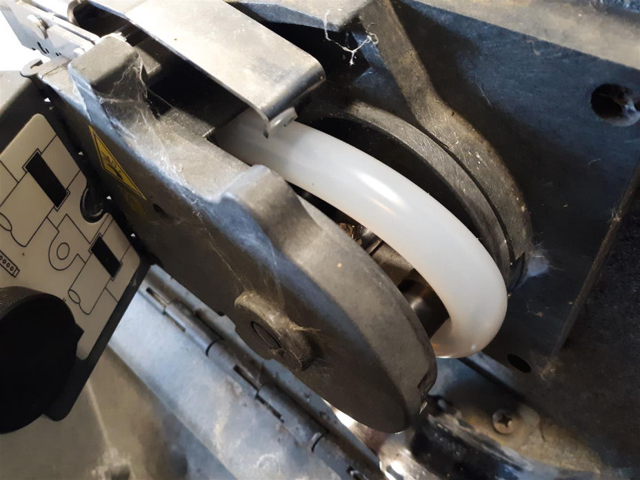
Teldyne ISCO Pump Tube Good Condition

Look for excessive wear caused by the pump rollers and for cracks along the sides of the tube. Cracks might not be apparent unless you flex or squeeze the tubing. If cracks or excessive wear are evident, replace the pump tube.

Example: Resetting the Pump Tube Alarm

A pump tube alarm should be set to notify you when the pump tube should be replaced. A pump tube should be replaced when it begins to show signs of wear, long before the tube wall fails.

Step 1

From the Main Menu screen select CONFIGURE.

Step 2

Step through the Configure options until you see the TUBING LIFE display. Press Enter

Step 3

The sampler briefly displays the current pump count information. Line one lists the pump counts since the last reset. Line two lists the current alarm setting. The screen will advance automatically.

Step 4

To reset the counter to zero, select YES. Always reset the counter after replacing a pump tube. Select NO when merely checking the current count. 

Step 5

You can modify the pump tube alarm setting to tailor it to your needs. The factory default setting is 1,000,000 pump counts. However you may experience tube wear more or less frequently. Change the pump-count alarm setting by typing the first two digits of the new setting. The sampler accepts entries between 1 and 99. For example, to increase the count to 1,500,000, enter 15.

Address

10633 County Road 26
Blair, NE 68008

Request Information

Information or quote request